Address
304 North Cardinal St.
Dorchester Center, MA 02124
Work Hours
Monday to Friday: 7AM - 7PM
Weekend: 10AM - 5PM
Address
304 North Cardinal St.
Dorchester Center, MA 02124
Work Hours
Monday to Friday: 7AM - 7PM
Weekend: 10AM - 5PM
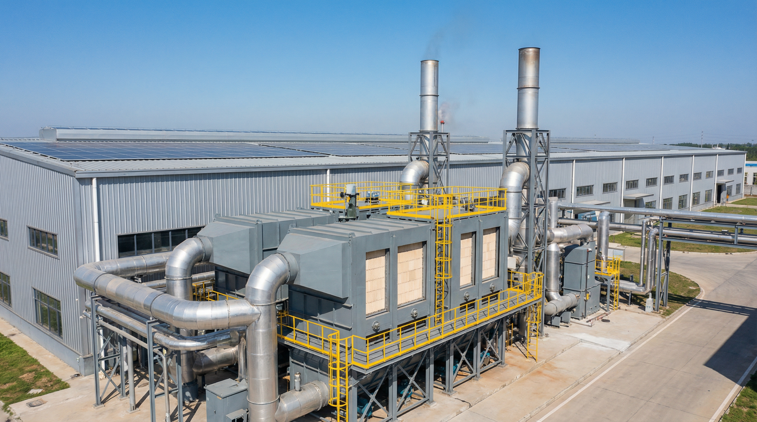
Pre-engineered RTO solutions for industrial VOC emission control with high thermal efficiency and stable continuous operation.
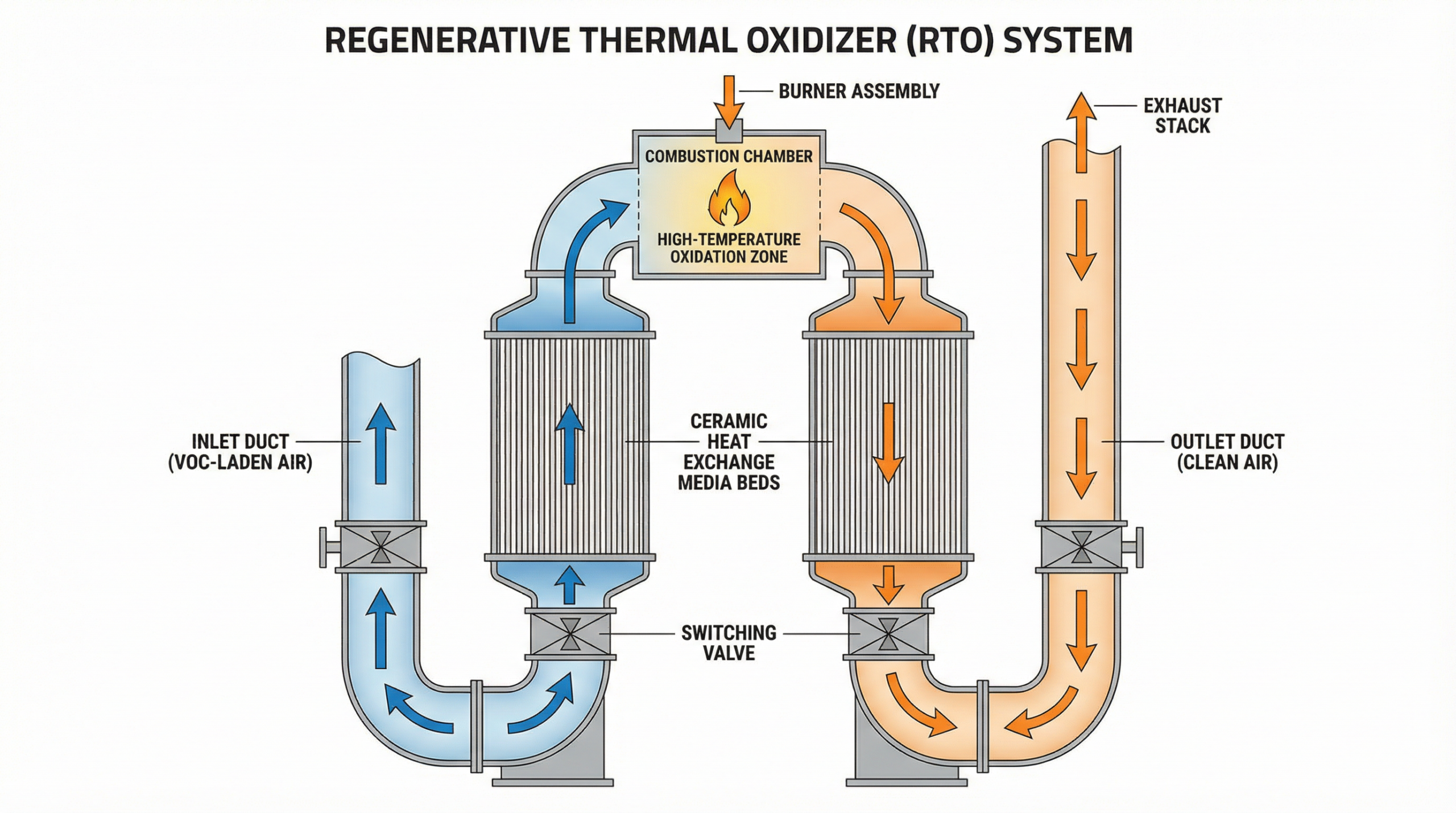
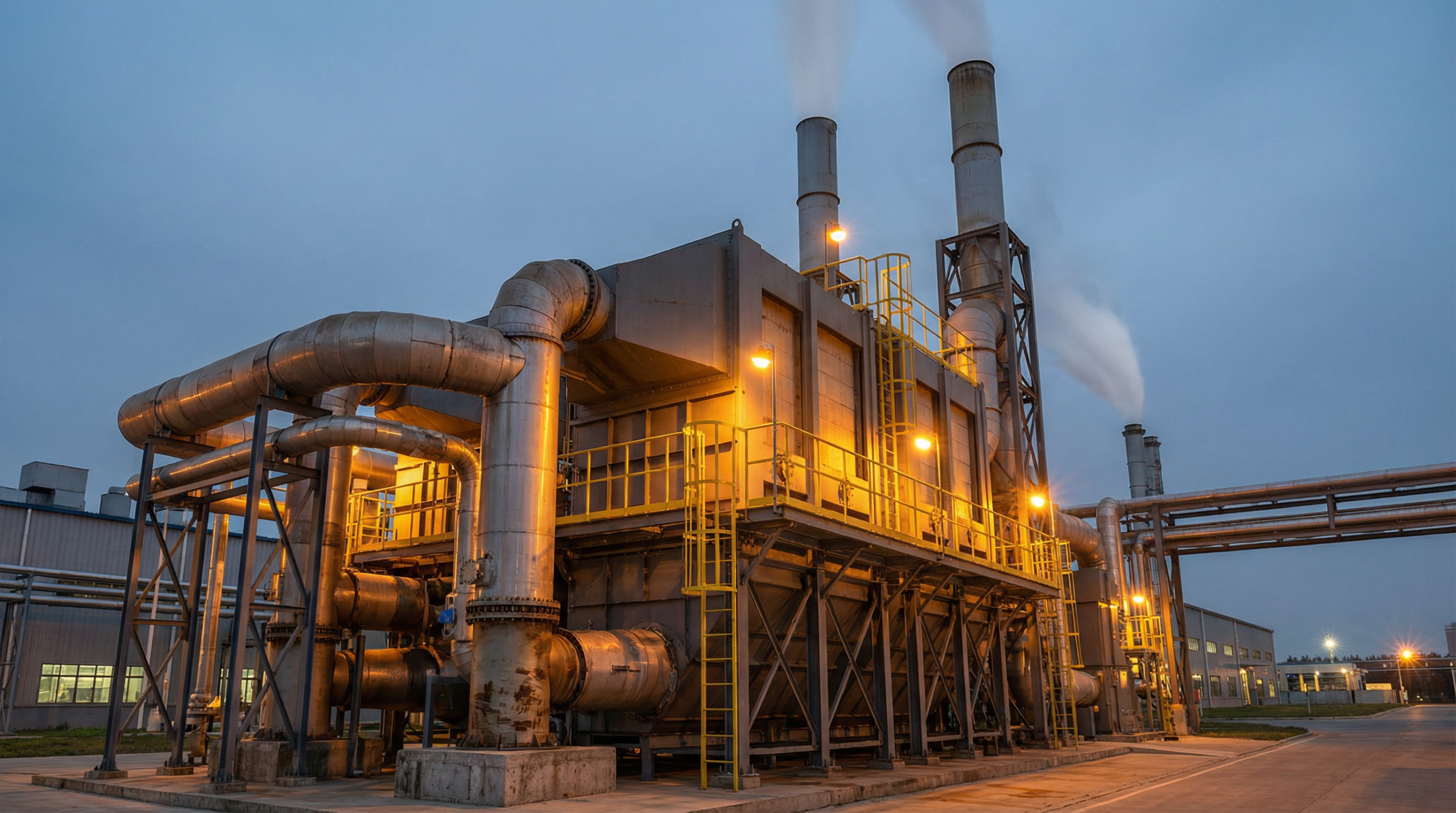
Standard Regenerative Thermal Oxidizer (RTO) systems are pre-engineered thermal oxidation units designed to destroy volatile organic compounds (VOCs) and odorous compounds in industrial exhaust streams. VOC-laden air is drawn into the system, preheated by ceramic heat exchange media, and then directed into a high-temperature combustion chamber where oxidation occurs at 760–820°C (1400–1510°F), converting VOC molecules into CO₂ and H₂O.
The regenerative design uses alternating ceramic beds to capture and return thermal energy to incoming gas, achieving up to 95% heat recovery. This significantly reduces supplemental fuel consumption compared to direct-fired thermal oxidizers. Standardized skid and chamber layouts simplify installation, commissioning, and long-term maintenance, making them suitable for a wide range of industrial VOC abatement applications.
For broader context on regenerative thermal oxidizer technology, see our RTO Systems overview. For a comparison of available VOC abatement technologies, visit our VOC Treatment Systems page.
Each component is engineered for reliable thermal oxidation performance and long-term industrial operation.
🔥
High-temperature oxidation zone operating at 760–820°C where VOC destruction occurs. Refractory-lined construction ensures thermal stability and long service life.
🧱
High-density ceramic saddle or structured media that capture and transfer thermal energy between exhaust cycles, enabling up to 95% heat recovery for reduced fuel consumption.
⚙️
Automated poppet or rotary valves control airflow routing through heat exchange beds. Timed switching cycles ensure continuous thermal oxidation and balanced VOC destruction efficiency.
🔧
Provides supplemental heat during system startup and low VOC concentration conditions. Natural gas or LPG-compatible burner with modulating control for precise temperature management.
🖥️
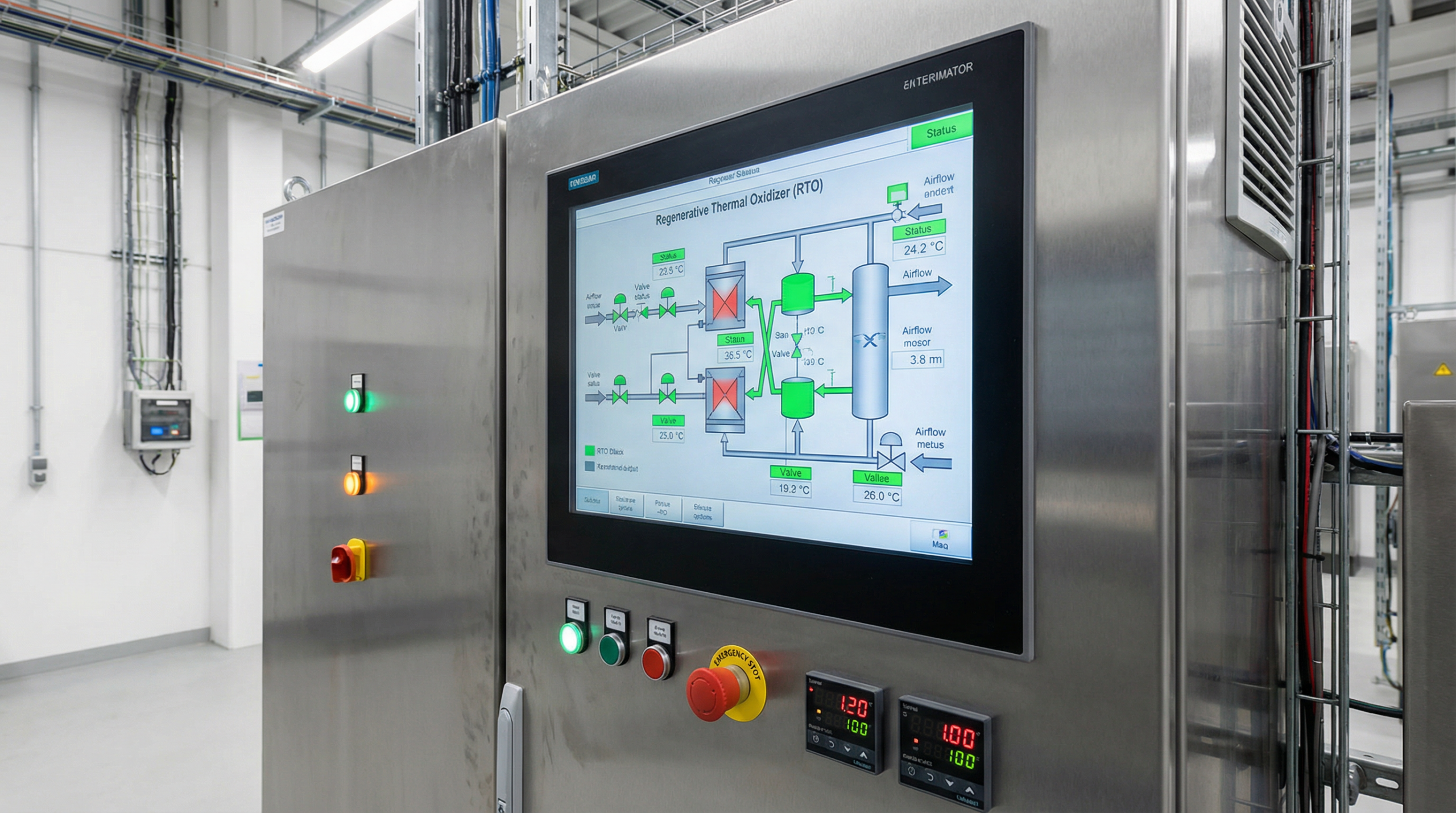
PLC-based automation with HMI touchscreen for real-time monitoring of temperature, valve status, and airflow. Supports remote monitoring, alarm management, and emission data logging.
🏭
Releases treated, compliant air to atmosphere. Stack design accounts for dispersion modeling and emission monitoring port requirements per local regulatory standards.
The following parameters represent typical design ranges for standard RTO configurations. Actual specifications are determined through engineering assessment of site-specific exhaust conditions.
* Parameters are indicative and subject to final engineering review. Contact our engineering team for site-specific sizing and compliance assessment.
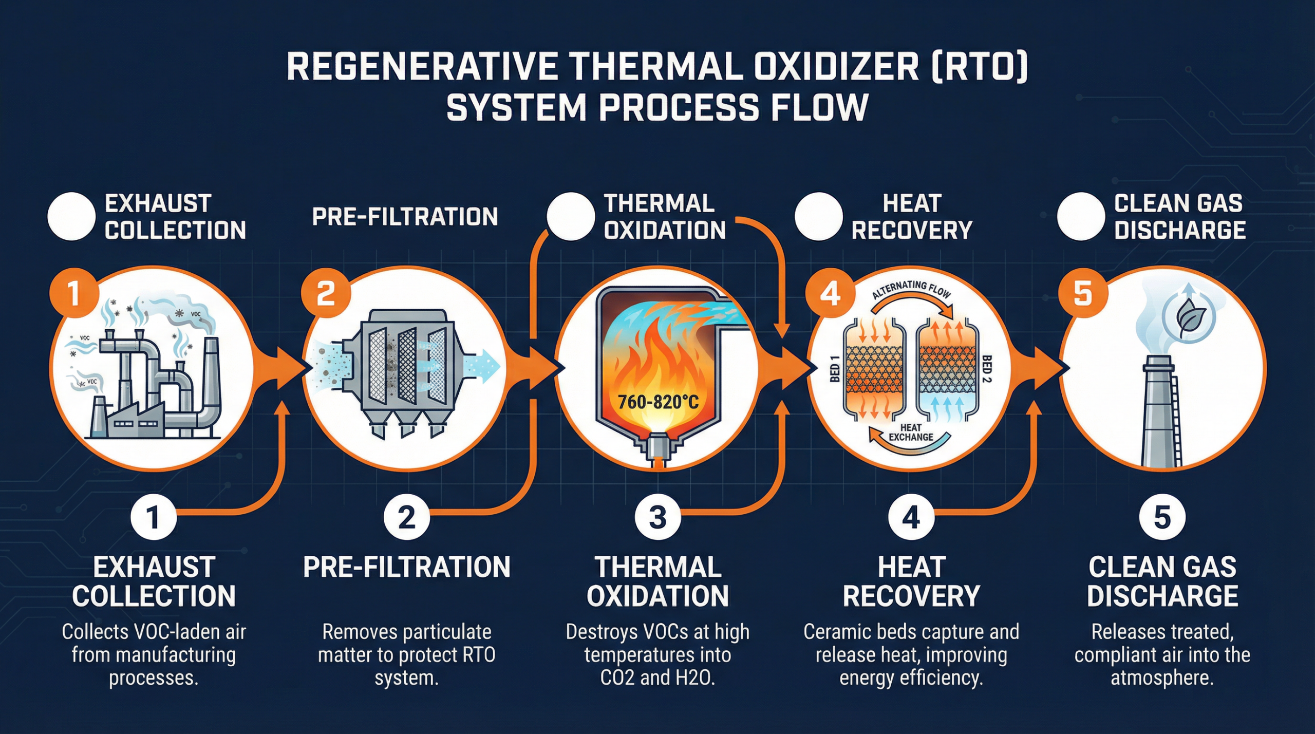
A five-stage treatment sequence ensures complete VOC destruction and energy-efficient operation from source capture to compliant discharge.
01
VOC-laden exhaust air is captured at source via dedicated ductwork and routed to the RTO inlet. Proper hood and duct design minimizes dilution air and optimizes VOC concentration.
02
Particulate filters or mist eliminators remove solids and liquid droplets that could foul ceramic media. Pre-treatment requirements depend on exhaust stream composition.
03
Preheated air enters the combustion chamber at 760–820°C. VOC molecules are oxidized into CO₂ and H₂O, achieving destruction efficiency ≥95% under design conditions.
04
Hot treated gas passes through the second ceramic bed, transferring thermal energy to the media. On the next cycle, incoming cold gas is preheated by this stored energy, reducing fuel demand.
05
Treated air meeting regulatory emission limits is discharged through the exhaust stack. Continuous emission monitoring (CEMS) can be integrated for real-time compliance verification.
✅
Achieves ≥95% VOC destruction efficiency under design operating conditions, meeting stringent emission standards across major regulatory frameworks including EPA, EU IED, and local equivalents.
✅
Up to 95% thermal recovery through ceramic heat exchange media significantly reduces supplemental fuel consumption compared to direct-fired thermal oxidizers, lowering long-term operating costs.
✅
Pre-engineered skid-mounted configurations reduce on-site installation time and simplify future maintenance access. Modular chamber design supports capacity expansion when process requirements change.
✅
Designed for 24/7 continuous duty in demanding industrial environments. Automated valve switching and PLC control maintain stable combustion temperature across varying VOC load conditions.
✅
Standard configurations are designed to meet VOC emission limits under EPA 40 CFR Part 63, EU Industrial Emissions Directive (IED 2010/75/EU), and equivalent national standards.
✅
Two-chamber and three-chamber configurations available to balance thermal efficiency, valve switching frequency, and airflow capacity requirements for different industrial applications.
Standard RTO systems are deployed across a range of industries with regulated VOC emission requirements.
🚗
Paint booth exhaust, primer curing ovens, and topcoat application lines generate solvent-laden air requiring continuous VOC abatement.
⚗️
Reactor vents, storage tank breathing losses, and process exhaust streams from chemical manufacturing require reliable thermal oxidation for compliance.
🎨
Flexographic, gravure, and offset printing operations, along with industrial coating lines, produce solvent exhaust streams well-suited to standard RTO treatment.
🏭
Electronics assembly, pharmaceutical manufacturing, and food processing facilities with odorous or solvent-laden exhaust streams benefit from standard RTO configurations.
Evaluate alternative RTO configurations and VOC treatment technologies to identify the most suitable solution for your process requirements.
Technical questions about standard RTO system selection, performance, and operation.
Standard RTO systems achieve VOC destruction efficiencies of ≥95% under design operating conditions. Actual efficiency depends on combustion chamber temperature, residence time, and the specific VOC compounds present in the exhaust stream. For applications requiring higher destruction efficiencies (≥99%), extended residence time chambers or catalytic configurations may be evaluated.
The regenerative heat exchange cycle captures thermal energy from outgoing treated gas and transfers it to incoming cold exhaust via ceramic media beds. With up to 95% thermal recovery, the supplemental burner only needs to maintain the temperature differential, rather than heating the entire gas stream from ambient. This substantially reduces natural gas or fuel consumption compared to direct-fired thermal oxidizers, particularly at moderate to high airflow volumes.
Standard RTO systems are appropriate when exhaust airflow, VOC concentration, and temperature fall within pre-engineered design ranges, and when installation space and utility connections are compatible with skid-mounted configurations. Custom RTO systems are required for unusual exhaust compositions, multi-source integration, space-constrained installations, or applications with non-standard emission compliance requirements. An engineering assessment of your process data will determine the appropriate approach.
Standard RTO systems are widely used in automotive paint and coating lines, chemical processing plants, flexographic and gravure printing facilities, pharmaceutical manufacturing, electronics assembly, and food processing operations. Any industrial process generating continuous VOC-laden exhaust within the standard airflow and concentration range is a potential application. Refer to our VOC Control Applications section for industry-specific guidance.
RTO sizing requires the following process data: total exhaust airflow volume (ACFM or Nm³/h), VOC type and concentration (mg/Nm³ or ppm), inlet temperature, particulate content, and applicable emission limits. Our engineering team reviews this data to determine the appropriate chamber size, ceramic bed volume, burner capacity, and control configuration. To begin the sizing process, submit your project details for an engineering assessment.
Provide your airflow rate, VOC concentration, and emission requirements. Our engineering team will evaluate a suitable standard RTO configuration for your facility.
For broader technology comparison, visit our RTO Systems overview or VOC Treatment Systems page.
Our engineering team will respond within 24 hours.